Dalam produksi dan pengujian akhir lini jok mobil, produsen menghadapi sejumlah tantangan yang harus diatasi untuk memastikan standar kualitas tertinggi.
Hal ini mencakup pengujian fitur yang tidak dapat dibedakan secara elektrik/optik, seperti fungsi peralihan lordosis atau sakelar poros, di mana malfungsi sulit dibedakan dari aktuasi yang salah. Parameter pengujian yang didefinisikan secara sempit seperti gaya uji dan posisi pengujian harus dipantau dan didokumentasikan secara ketat. Proses pengoperasian dan pengujian yang tidak ergonomis seperti memutar, mengangkat, atau memompa dapat menimbulkan ketegangan fisik pada personel penguji dan selanjutnya mengurangi ketersediaan staf yang berkualifikasi.
')
// -->
')
// -->
By using robots and camera systems, these tasks can be mastered to increase quality and efficiency in production.
Case study: Robot automation at a leading automotive supplier
An end-of-line test station for car seats (Fig. 1) consists of various components that interact to check the quality and conformity of the car seats produced. The test item car seat (1) is transported on a goods carrier (2) on the production line and moved into the EOL test station at the end of the production process.
Here is a test system for functional testing (3), which is connected to the car seat and performs all test tasks. These tasks are conventionally visualized for the operator performing them and, if necessary, confirmed on the test monitor.
At the automated test stand, a robotic arm is integrated into the test system to perform the manual test processes in a coordinated manner. It is supported by optical measurement systems, such as cameras and lasers, which increase repeatability, and the safety components (4), which ensure that the test station complies with the applicable safety standards and that accidents or injuries are prevented.
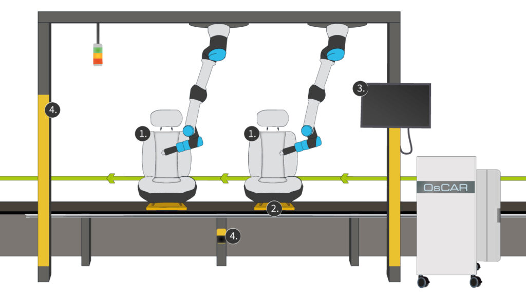
Fig. 1: End-of-line test station for car seats
One of the greatest challenges in the automation of manufacturing processes and quality inspections is the correct determination of the position of the test specimen. This is to be regarded as a complex body with several degrees of freedom in positioning. The test specimen is subject to many tolerances in the production process, which can lead to a large shift in the feature position.
At the automation station, we assume three coordinate systems for position description (Fig. 2). The robot coordinate system TCP (A), the DUT coordinate system (B) and the coordinate system of the workstation/ware carrier (C).
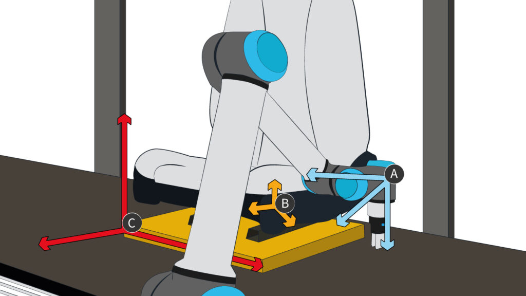
Fig. 2: Seat in x-y-z coordinate system – coordinate system seat/switch panel/TCP
The aim is to transfer the position of a feature from the DUT coordinate system B to the robot coordinate system A so that a specific waypoint p can be approached in this system. How precisely this waypoint must be determined depends on the application. For example, interactions with the switch panel of a car seat require a higher accuracy than the placement of a tennis ball in a basketball hoop.
Process capability reduced due to insufficient position determination
Correct position detection is important because it has a significant influence on the costs of the production process. Incorrect detection leads to an increased need for rework, longer cycle times due to repeat inspections and, in the worst case, even damage to the test specimen.
If, for example, adhesive is not applied correctly to the bonding surfaces, this component is unusable for the further production process and must be sorted out. The same applies to screw applications, which cannot carry out the process correctly if the position is incorrectly determined and therefore have to be reworked manually.
Here, it is not only the manual rework station that is a cost factor. Another quality check must also be integrated into the production process in order to detect such defects in the first place.
Depending on the process robustness, different deviations in the position determination are tolerable. The use of the different techniques or measures must therefore be considered in accordance with their implementation effort, the boundary conditions at the workplace and the target size.
Possibilities of position determination
There are various procedures for determining the correct position, which are used individually or in combination. First, the test specimen should be positioned as precisely as possible on the workpiece carrier in the workstation coordinate system. From this, the test specimen can be manipulated via force-guided approach with large tolerances and a suitable component/TCP structure. For more precise results, specific points of the coordinate system are measured tactilely using force sensors (workstation, test specimen) and finally specific features of the coordinate system are measured optically using a camera system (workstation, test specimen).
Create boundary conditions, position the test specimen precisely and reduce tolerances. In order to determine the position of the test specimen, we should assume certain boundary conditions for simplification. Creating these is by no means trivial and requires suitable means, which will only be briefly named in the following.
It is assumed for all coordinate systems that they are orthogonal to each other and that the offset only occurs in the position x-y-z and not in the orientation direction rx-ry-rz.
A transformation matrix is derived from specific test item characteristics to determine the test item displacement. If the DUT feature deviates too much from the taught-in standard, e.g. due to damage or incorrect assembly, the position will be determined incorrectly.
Ideally, the mechanical tolerances of these components are minimal. Unfortunately, this can often only be achieved at great expense for a complete production line; in particular, the transitions from the production line to the workpiece carrier and workpiece can have a high variance.
Often, existing production lines are also automated at a later stage. In addition to changed requirements in terms of space requirements and gripping space, the requirements for the positional accuracy of the test item at the EOL test station are not as high for the manual test process as they are for an automated process. Wear on stoppers, product carriers and clamps also further increase the positioning tolerances.
Therefore, for each automation process, the appropriate tools and the combination of the right material and tool geometry must be selected to enable, at best, force-controlled positioning.
Force controlled positioning
With force-controlled positioning, the test piece geometry is such that the position can be carried out via an insertion process.
For this purpose, the robot must be programmed in such a way that it is freely movable in at least one axial direction and can approach the test specimen with a defined force. The special combination of tool and test piece geometry then allows threading, e.g. insertion of the belt buckle tongue into the funnel-shaped belt buckle opening.
Tactile position recognition
If the test piece geometry is not suitable for force-controlled positioning, the test piece coordinate system can be made by probing certain test features using robot TCP.
The test specimen is to be probed in the axes in which a displacement of the Cartesian coordinate system is to be expected. The difference to the standard position is determined and used to shift the coordinate system of the test specimen.
The advantage is that no additional measuring equipment other than the robot with force sensor technology is required. The hardware and installation costs are thus reduced, and the maintenance effort decreases.
The prerequisite for this method is that the test specimen has accessible features (e.g., larger probing surfaces) which have the lowest possible error variance and via which a displacement in the x-y-z direction can be determined.
However, errors in the test item characteristic lead to an incorrect position determination and it is not possible to distinguish afterwards without aids whether the error lies with the test item or with the position determination.
Optical position detection
If the test object has optically unambiguously identified features (flat surfaces, reference shapes, etc.), optical position determination is possible. In this case, a feature is taught in the standard position and then the displacement to the standard position is determined by image recognition software.
The optical measuring method saves probing time and is less error-prone than tactile referencing, depending on the test specimen.
The disadvantage is that the camera image can be negatively influenced by lighting conditions, visual obstructions, color diversity (e.g., black on black feature) and the limitation in the integrability at the workplace. Often, integration into the robot arm is the simplest implementation.
In the application example for the quality inspection of the car seat of the company Göpel electronic, for example, a UR10e robot arm with integrated Robotiq Wrist Camera is used (Fig. 3). Feature shapes can be taught here using CAD files or simple geometric shapes (Fig. 4).
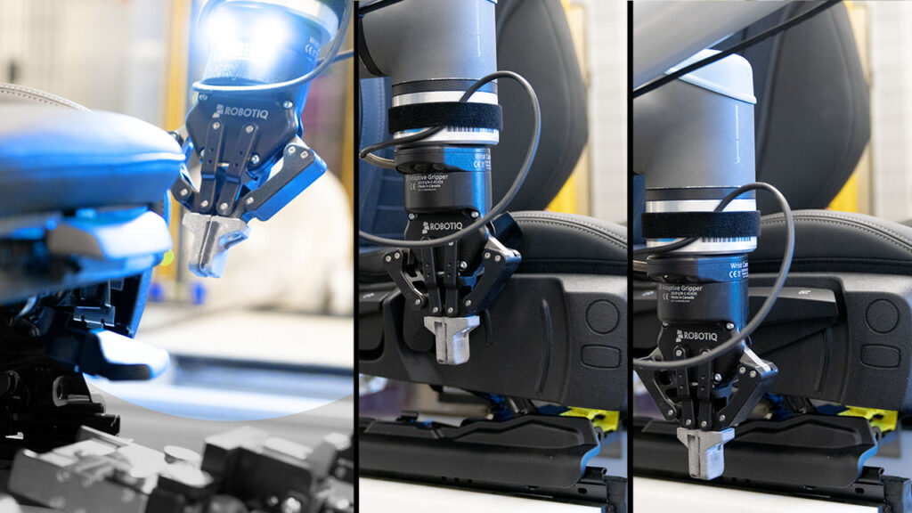
Fig. 3: Referencing sequence switch panel on the side for the car seat
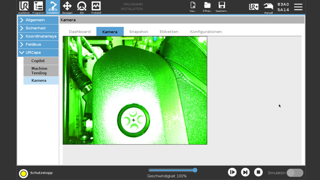
Fig. 4: Potential features of the car seat side switch panel
Position found – What now?
Once the displacement of the test item to the standard position has been determined, the test item coordinate system can now be displaced by the difference vector and the correct position can be controlled.
When determining the position, it is important to take into account the specific requirements of the process and the test piece geometry. This enables efficient quality inspection, reduces rework and scrap as well as additional quality inspections. This increases process capability, cost efficiency and product quality.